
Why Walkout Basements Belong on Floor 1—and Foundations on Floor 0—in Chief Architect

A walkout basement is one of those conditions that looks simple in section and becomes unnecessarily complicated the moment we try to force every piece of it onto a single floor in Chief Architect.

The better method is to separate the two systems according to what they actually represent:

  • Floor 1 is the occupied walkout level. It contains the basement rooms, slabs or framed floors, furred walls, regular exterior walls, retaining-wall conditions, and the stepped wall construction that belongs to the usable story.
  • Floor 0 is the foundation level. It contains the lower stem walls, footings, isolated piers, posts, girders, and other below-slab or below-floor support.

That division is not arbitrary. It produces a cleaner model, clearer drawings, more reliable labels, and more predictable area calculations.
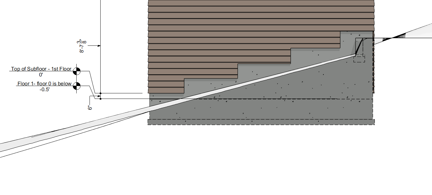
Stepped walkout foundation elevation

The stepped foundation continues below the Floor 1 subfloor while the occupied walkout remains on Floor 1.

Model the building, not just the concrete

In Chief Architect, floor numbers should describe the building organization—not simply the order in which concrete was poured. A walkout basement is occupied space. Even when part of its exterior enclosure is concrete, the walkout still behaves like a story: it has rooms, doors, windows, wall finishes, floor systems, dimensions, and area.

Floor 0, by contrast, is normally a foundation plan. It describes the structure supporting the occupied level above it.

When both systems are placed on Floor 0, the model has to make one floor behave simultaneously as a basement plan, a foundation plan, and a support plan. That creates avoidable conflicts in saved plan views, layer control, dimensions, reference displays, automatic labels, and area reporting.

Keeping the occupied walkout on Floor 1 lets its Top of Subfloor remain the controlling story reference. The stepped foundation can continue below that elevation and follow the site without redefining the walkout as foundation-only space.

Use the right Floor 1 wall for each condition

A walkout perimeter is rarely one uniform wall. As grade falls, the enclosure may transition through several conditions:

  • a full-height concrete or retaining wall;
  • a concrete stem wall with an interior furred wall;
  • a stepped pony wall with concrete below and framed exterior wall above;
  • a conventional framed exterior wall where the floor is fully above grade.

Those are all Floor 1 enclosure conditions because they define the occupied walkout level. The exact wall type may change, but the floor assignment does not need to.

For the common stepped condition, use a pony-wall assembly on Floor 1. The lower pony wall is the concrete stem-wall type; the upper pony wall is the normal exterior wall type. This gives us a continuous wall in plan while allowing the top of the concrete to be broken and stepped directly in elevation.
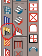
PPX18 walkout pony-wall toolbar tool

PPX18 includes a walkout pony-wall tool designed as the starting assembly for this condition.

The supplied PPX18 assembly uses an 8-inch concrete stem wall furred with 2x4 framing and drywall below, paired with a siding wall and matching interior furring above. Intentional air gaps align the concrete and framing while keeping the gypsum-board face continuous. The outside remains breakable for the stepped foundation; the inside reads as a coordinated finished wall.

Where the condition is not a pony wall, use the appropriate regular wall, furred wall, or retaining wall on Floor 1. The goal is not to use one wall type everywhere. The goal is to keep the occupied enclosure together on the occupied floor.

Why Floor 0 still matters

Floor 0 carries the foundation that is truly below the walkout story: lower stem walls, widened concrete walls, footings, pads, piers, posts, girders, and support below framed or cantilevered portions.
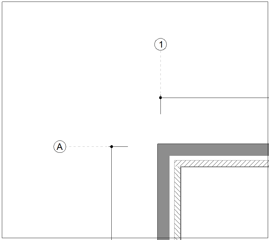
Floor 1 walkout plan

Floor 1 can isolate the walkout walls, rooms, and aligned interior furring.
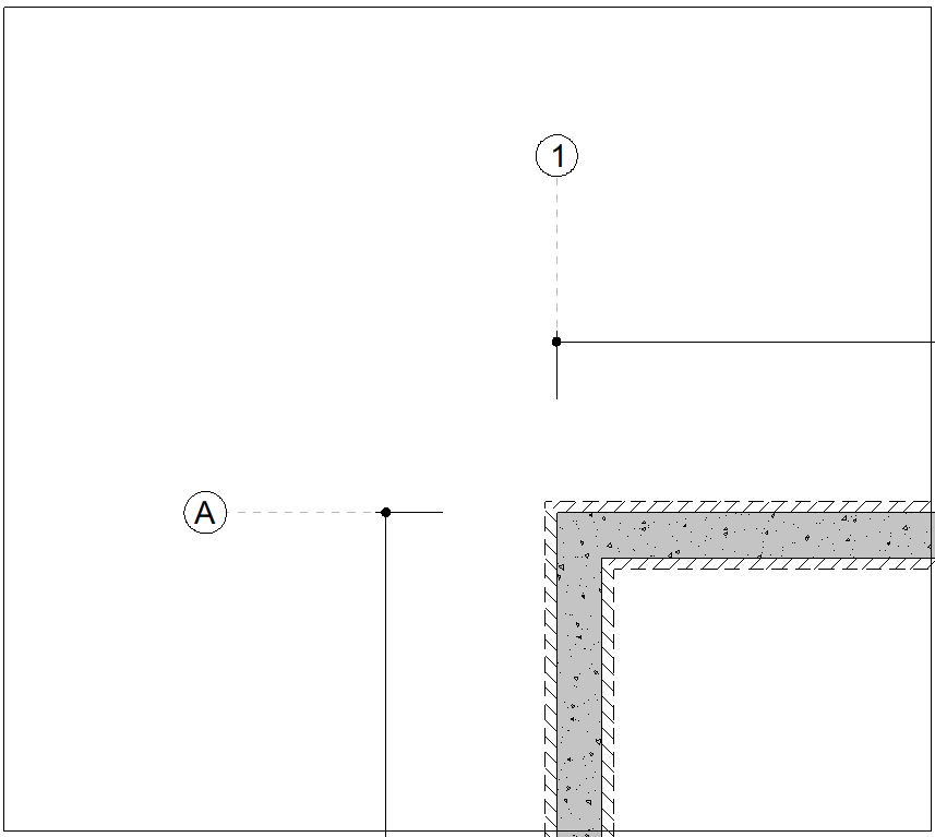
Floor 0 foundation plan

Floor 0 can independently show the lower concrete stem walls, footings, and foundation-only construction.

This is especially valuable when the wall below the slab is wider than the stepped wall above it. Floor 0 can carry the wider lower stem and footing while Floor 1 carries the narrower wall and its interior finish. If the lower foundation needs another thickness change, Floor 0 can even use its own pony-wall condition to create an additional ledge.
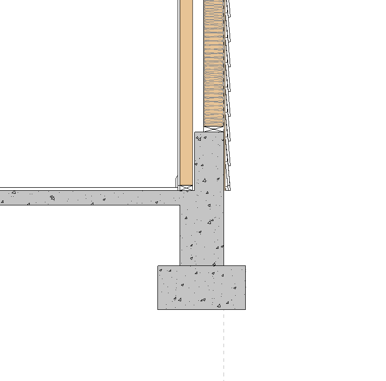
Walkout stem-wall section

The furred walkout wall, slab, lower stem, and footing remain separate and controllable.
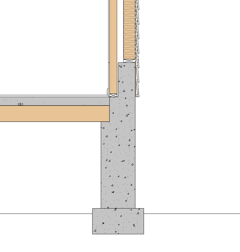
Multi-ledge walkout foundation

Complex multi-ledge foundations can be divided logically between the Floor 1 enclosure and Floor 0 support.

Trying to force every transition into one wall on one floor usually produces a fragile model. Separating the systems gives each ledge, wall thickness, and support condition a clear purpose.

Mixed slabs, framed floors, and crawlspaces become easier

Walkout projects often combine several structural systems. One portion may be slab-on-grade while another is wood-framed over a crawlspace, extends over a retaining wall, cantilevers above grade, or transitions to posts and girders.

With the walkout on Floor 1, those occupied floor conditions can coexist where they belong. Floor 0 remains available for the isolated supports below the framed portions. We avoid forcing a complicated split-floor model and a complete foundation model onto the same level.

Footings that support an at-grade or crawlspace condition may still be displayed with the Floor 1 walkout plan when useful. The distinction is not an inflexible visibility rule. It is a modeling structure that lets saved plan views, layer sets, and reference displays present the right information for each drawing.

Cleaner plans with less layer-set gymnastics

Once Floor 1 and Floor 0 have distinct jobs, the standard PPX18 saved plan views, layer sets, and dimension defaults can do more of the work.

Floor 1 can show the occupied plan, furring, pony-wall portions, doors, windows, room labels, and dimensions without every lower footing competing for attention. Floor 0 can show the foundation-only construction without the finished walkout plan obscuring it.

We no longer need a special layer set simply to pretend a pony wall is sometimes an upper wall and sometimes a foundation wall. We can show both pony-wall portions—or either portion—on Floor 1 as the drawing requires, while controlling the lower foundation independently on Floor 0.

Reference displays also become easier to understand because the referenced floor is not competing with another complete model occupying the same level.

The labeling problem: Floor 1 is the basement, and Floor 2 is the main level

This modeling method creates one genuine documentation challenge: Chief Architect still knows the stories by their internal floor numbers. In a walkout model, the occupied basement is built on Floor 1, even though the finished drawings may need to call it Basement, Lower Level, or Walkout Level. The main living level is therefore modeled on Floor 2, even though the plans should typically identify it as the Main Level or First Floor.

If those raw floor numbers are allowed to flow directly into view titles, the labels become confusing. A Floor 1 plan can be incorrectly presented as the first-floor plan, while the actual main-level Floor 2 view can appear to be the second floor. Every dependent upper story is then shifted by one in the construction-document naming convention.

There are three ways to handle this:

  1. Rename the Saved Plan Views manually. This works, but every affected plan, framing, electrical, reflected-ceiling, foundation-reference, and layout view must remain coordinated as the project changes.
  2. Create a custom macro script. The script can test whether the project has a walkout basement and conditionally translate Chief Architect's floor references into the office's desired story names. An AI coding service can help create this logic, but the result still needs to be tested against the office's templates, layout labels, and every project condition.
  3. Use the automation already built into the Rabbitt Design system. The Pro Plan X18 template includes macro-driven labeling conventions for walkout projects. In PPX18 Layout, open Project Information, choose Layout Options, set Walkout True False to True, and enter the preferred lower-level name in Walkout Name.

The PPX18 macros then remap the floor-based view labels so Floor 1 can be called Basement, Lower Level, or Walkout, Floor 2 can be identified as the main level, and the upper-story labels continue in the expected sequence. We preserve the technically useful Chief Architect floor structure without forcing the construction documents—or the person reading them—to think in Chief Architect's internal numbering system.

Area analysis stays predictable

Floor 0 is commonly excluded from selected area-analysis schedules because it normally represents unconditioned foundation space. If we place the occupied walkout on Floor 0, we either lose legitimate basement area or have to build exceptions that risk counting foundation-only space.

Placing the occupied basement on Floor 1 allows it to remain in the intended conditioned or building-area calculations. Floor 0 can remain excluded as foundation-only construction. The reported totals follow the actual use of the building instead of the accident of where the foundation was modeled.

The recommended assignment

Floor 1: walkout rooms, occupied slabs or framed floors, stepped pony walls, furred concrete walls, conventional exterior walls, retaining-wall enclosure conditions, windows, doors, finishes, and other story-level construction.

Floor 0: lower stem walls, widened foundation walls, footings, isolated piers, posts, girders, and foundation-only support below the walkout.

Layout Options: enable the walkout value and provide the preferred walkout-level name so automatic view labels follow the model structure.

This approach does not eliminate the need to verify the actual project. Always check plan views, sections, wall intersections, dimensions, labels, and reported areas. What it does eliminate is a great deal of unnecessary complexity. By putting the occupied walkout on Floor 1 and the supporting foundation on Floor 0, Chief Architect can model the building the way it is designed, document it the way it is constructed, and report it the way it is used.

For the illustrated workflow and current PPX18 instructions, see the Walkout Basements chapter of the PPX18 Manual.A walkout basement is one of those conditions that looks simple in section and becomes unnecessarily complicated the moment we try to force every piece of it onto a single floor in Chief Architect.

The better method is to separate the two systems according to what they actually represent:

  • Floor 1 is the occupied walkout level. It contains the basement rooms, slabs or framed floors, furred walls, regular exterior walls, retaining-wall conditions, and the stepped wall construction that belongs to the usable story.
  • Floor 0 is the foundation level. It contains the lower stem walls, footings, isolated piers, posts, girders, and other below-slab or below-floor support.

That division is not arbitrary. It produces a cleaner model, clearer drawings, more reliable labels, and more predictable area calculations.

Stepped walkout foundation elevation

The stepped foundation continues below the Floor 1 subfloor while the occupied walkout remains on Floor 1.

Model the building, not just the concrete

In Chief Architect, floor numbers should describe the building organization—not simply the order in which concrete was poured. A walkout basement is occupied space. Even when part of its exterior enclosure is concrete, the walkout still behaves like a story: it has rooms, doors, windows, wall finishes, floor systems, dimensions, and area.

Floor 0, by contrast, is normally a foundation plan. It describes the structure supporting the occupied level above it.

When both systems are placed on Floor 0, the model has to make one floor behave simultaneously as a basement plan, a foundation plan, and a support plan. That creates avoidable conflicts in saved plan views, layer control, dimensions, reference displays, automatic labels, and area reporting.

Keeping the occupied walkout on Floor 1 lets its Top of Subfloor remain the controlling story reference. The stepped foundation can continue below that elevation and follow the site without redefining the walkout as foundation-only space.

Use the right Floor 1 wall for each condition

A walkout perimeter is rarely one uniform wall. As grade falls, the enclosure may transition through several conditions:

  • a full-height concrete or retaining wall;
  • a concrete stem wall with an interior furred wall;
  • a stepped pony wall with concrete below and framed exterior wall above;
  • a conventional framed exterior wall where the floor is fully above grade.

Those are all Floor 1 enclosure conditions because they define the occupied walkout level. The exact wall type may change, but the floor assignment does not need to.

For the common stepped condition, use a pony-wall assembly on Floor 1. The lower pony wall is the concrete stem-wall type; the upper pony wall is the normal exterior wall type. This gives us a continuous wall in plan while allowing the top of the concrete to be broken and stepped directly in elevation.

PPX18 walkout pony-wall toolbar tool

PPX18 includes a walkout pony-wall tool designed as the starting assembly for this condition.

The supplied PPX18 assembly uses an 8-inch concrete stem wall furred with 2x4 framing and drywall below, paired with a siding wall and matching interior furring above. Intentional air gaps align the concrete and framing while keeping the gypsum-board face continuous. The outside remains breakable for the stepped foundation; the inside reads as a coordinated finished wall.

Where the condition is not a pony wall, use the appropriate regular wall, furred wall, or retaining wall on Floor 1. The goal is not to use one wall type everywhere. The goal is to keep the occupied enclosure together on the occupied floor.

Why Floor 0 still matters

Floor 0 carries the foundation that is truly below the walkout story: lower stem walls, widened concrete walls, footings, pads, piers, posts, girders, and support below framed or cantilevered portions.

Floor 1 walkout plan

Floor 1 can isolate the walkout walls, rooms, and aligned interior furring.

Floor 0 foundation plan

Floor 0 can independently show the lower concrete stem walls, footings, and foundation-only construction.

This is especially valuable when the wall below the slab is wider than the stepped wall above it. Floor 0 can carry the wider lower stem and footing while Floor 1 carries the narrower wall and its interior finish. If the lower foundation needs another thickness change, Floor 0 can even use its own pony-wall condition to create an additional ledge.

Walkout stem-wall section

The furred walkout wall, slab, lower stem, and footing remain separate and controllable.

Multi-ledge walkout foundation

Complex multi-ledge foundations can be divided logically between the Floor 1 enclosure and Floor 0 support.

Trying to force every transition into one wall on one floor usually produces a fragile model. Separating the systems gives each ledge, wall thickness, and support condition a clear purpose.

Mixed slabs, framed floors, and crawlspaces become easier

Walkout projects often combine several structural systems. One portion may be slab-on-grade while another is wood-framed over a crawlspace, extends over a retaining wall, cantilevers above grade, or transitions to posts and girders.

With the walkout on Floor 1, those occupied floor conditions can coexist where they belong. Floor 0 remains available for the isolated supports below the framed portions. We avoid forcing a complicated split-floor model and a complete foundation model onto the same level.

Footings that support an at-grade or crawlspace condition may still be displayed with the Floor 1 walkout plan when useful. The distinction is not an inflexible visibility rule. It is a modeling structure that lets saved plan views, layer sets, and reference displays present the right information for each drawing.

Cleaner plans with less layer-set gymnastics

Once Floor 1 and Floor 0 have distinct jobs, the standard PPX18 saved plan views, layer sets, and dimension defaults can do more of the work.

Floor 1 can show the occupied plan, furring, pony-wall portions, doors, windows, room labels, and dimensions without every lower footing competing for attention. Floor 0 can show the foundation-only construction without the finished walkout plan obscuring it.

We no longer need a special layer set simply to pretend a pony wall is sometimes an upper wall and sometimes a foundation wall. We can show both pony-wall portions—or either portion—on Floor 1 as the drawing requires, while controlling the lower foundation independently on Floor 0.

Reference displays also become easier to understand because the referenced floor is not competing with another complete model occupying the same level.

Automatic labels finally match the drawings

PPX18 can recognize this floor arrangement in Layout. Open Project Information, choose Layout Options, set Walkout True False to True, and enter the desired lower-level name in Walkout Name.

This remaps the floor-based view labels so Floor 1 can be called Basement, Lower Level, Walkout, or whatever the office standard requires, while Floor 0 remains the foundation level. We keep the technically useful floor structure without forcing the construction documents to use Chief Architect's default floor names.

Area analysis stays predictable

Floor 0 is commonly excluded from selected area-analysis schedules because it normally represents unconditioned foundation space. If we place the occupied walkout on Floor 0, we either lose legitimate basement area or have to build exceptions that risk counting foundation-only space.

Placing the occupied basement on Floor 1 allows it to remain in the intended conditioned or building-area calculations. Floor 0 can remain excluded as foundation-only construction. The reported totals follow the actual use of the building instead of the accident of where the foundation was modeled.

The recommended assignment

Floor 1: walkout rooms, occupied slabs or framed floors, stepped pony walls, furred concrete walls, conventional exterior walls, retaining-wall enclosure conditions, windows, doors, finishes, and other story-level construction.

Floor 0: lower stem walls, widened foundation walls, footings, isolated piers, posts, girders, and foundation-only support below the walkout.

Layout Options: enable the walkout value and provide the preferred walkout-level name so automatic view labels follow the model structure.

This approach does not eliminate the need to verify the actual project. Always check plan views, sections, wall intersections, dimensions, labels, and reported areas. What it does eliminate is a great deal of unnecessary complexity. By putting the occupied walkout on Floor 1 and the supporting foundation on Floor 0, Chief Architect can model the building the way it is designed, document it the way it is constructed, and report it the way it is used.

For the illustrated workflow and current PPX18 instructions, see the Walkout Basements chapter of the PPX18 Manual.

Next
Next

The AI Resource Handbook: A Blog Series - Introduction